The other day, in a meeting with a system Integrator from Trivandrum (He has been a great supporter of our products and has given us tons of valuable feedback and some good business too) we were asked if it was OK to use a 60 Cell panel with 24 V battery system and a PWM charger. We had to tell him that it would be better to use a 72 Cell Panel with a 24V battery system esp with a PWM charger. (Similarly a 36 Cell panel with a 12V battery system).
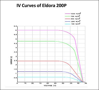
The reason is simple.The Current – Voltage curves of the 60 Cell Panel seem to indicate that the Maxi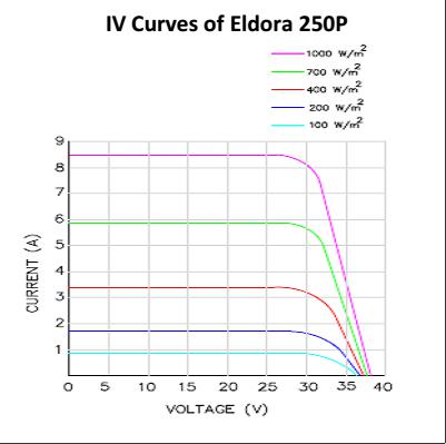 mum power point is at 30V. Given that the 24V batteries are going to operate at a maximum of 28V and therefore the Maximum power Voltage is higher than the highest operating battery Voltage, (See the I-V curve on the left – this one is from the Panel data sheet of Vikram Solar http://www.vikramsolar.com/eldora-prime-series.aspx) the PWM charger ought to have no difficulty charging the batteries at all the various Battery voltages of a 24V battery system. However – these curves are at STC (Standard Test conditions ) and even at STC, at lower Solar availability, the maximum power point has shifted to a lower Voltage value. And real life conditions are very different from STC . For one, the ambient temperatures when we get 1000W/m2 of Solar power is likely to be much higher than 25 deg C that the STC uses. The actual cell temperature is probably close to 65- 70 deg C. Panel data sheets refer to the drop in Voc and the Vmpp with a temperature coefficient. (e.g the same Panel data sheet the Temperature coefficient is mentioned as -0.31% per deg C. Apply that to the STC values and we find that the actual maximum power point is now nearer 24-26V and not the 30V that we see in the standard I-V curves. Now with battery voltage at 24V or more – the PWM charger is forced to operate to the right of the knee instead of the left of the knee. ( in the curve above , the maximum power point is close to the knee of the curves).
The problem with operating at the right of the knee instead of the left of the knee is obvious once we look at the curves above. On the right of the knee, we see that the curve is dropping sharply and that means that a small shift to the right on Voltage will mean a large drop in available Current – and therefore the Power ( Power: multiply I and V). Whereas if we operate to the left of the knee- the value of Current (I) does not change much and we end up getting more power in the exact same conditions. We may even be operating on the knee and getting the maximum power with the PWM charger if the knee is ‘right’ enough. Take a look at a similar IV curve for a 72 Cell panel below. Even under real life conditions, we are likely to operate at the left of the knee and that is why it is advisable to use a 72 cell panel with 24V battery systems and 36 cell panels with 12V battery systems.