
In January, I had posted the last update on my solar power project, that I have been working for quite some time now. Over time, working in the evenings on workdays and almost through the day on weekends/holidays, I have finally started my own solar power generation generation system, that is now functional, partially. The tracker that had been in testing for around three months now, finally got to host what it had been designed for, and all this while, was carrying a really small solar module.
Just a few days back (20th of April, 2016), I finally installed the solar modules on the tracking platform, and hooked it up to the existing power backup system, I had installed some time back for my home. And the result, free power for my home, which, for now, will service the loads partially, thereby resulting in a reduced power bill for the utility power I have been using. Over the period, I have planned to upscale the capacity of my solar power system, which, will then be self sufficient to provide power for all the needs of my house.
Now, the system has been installed and is functioning, what’s left is to begin the tracking system, which, for now is non functional, because the tracking system appeared to be ill equipped to handle such a large load, and thus, I am tweaking it a bit to make it capable enough to do what is intended to, without breaking a sweat. Since this is something I am doing for the first time, and without any theoretical or practical knowledge, there was no way I could’ve anticipated what was in store for me, once I had the solar modules installed on the tracker, which, for the time it was working with that small module, appeared pretty capable enough to efficiently complete its task without a problem. This, I know, is a part and parcel of DIY, for you learn with what you do, and over time, there comes a point where you achieve perfection, and what you wanted to do, and this is what I have been trying to achieve.
Over time, I had to change a lot of things in the planned tracking system. To say the least, the entire idea of the tracking system we had planned to take up to work on, as we moved our application in the Mahindra Rise Prize’s Solar Challenge, has changed. The use of linear actuators has replaced one of the gear based mechanisms, again, this actuator based mechanism is up for an overhaul as we build ourselves a better, more capable actuating mechanism, just because we need to have a better one, and buying this one off the shelf is out of question. Why? Firstly, because these cost a bomb, and secondly, we do not have too many options to look for, because looking for parts like these needs a massive hunt for places which deal in such speciality parts, which, is a very great impediment in doing almost anything. Also, I had to improve the light sensor setup, improve the overall reaction to light changes over the sensors, and am required to add some more ways to make the tracker work better, be a completely autonomous system that is capable enough to do the tracking throughout the day, and reset itself back to east at dusk, to begin a new day of tracking, all on its own. What more in the store is a web based realtime monitoring system that lets me check out on vital stats of the system, from anywhere in the world with the help of a website that will be fed by a variety of sensors reading some vital stats of the system, viz Voltage and Current (both of which will give me the total output in watts), Cell Temperature, Location (in terms of direction of the tracking platform), a planned anemometer, which will be helpful in case of a storm, to keep the modules relatively safer.
Now the good part is, I have enquiries pouring in from neighbours and whoever can see my solar modules on the tracker, facing the sun, on my rooftop. Appears, this is also a chance where I could cash in the advantage I have, over the regular solar power system integrators, most of whom, just do a static installation, for a cost that is be more than double of what I had to shell out for this system.
Did I make you curious? In case you would like to take a look at the specifications to get to know this better, you can take a look below:
The components/parts I bought off the shelf:
| Part | Qty | Make/Specs |
|---|---|---|
| SOLAR MODULES | 2 Nos. | Canadian Solar 265 watt @ 24v (Another 40 watt 12v solar module to provide power supply for the tracking electronics) |
| SOLAR CHARGE CONTROLLER | 1 No. | Amberroot ReHUB MPPT (12/24v, 40A) |
| INVERTOR | 1 No. | Luminous 1500VA Pure Sine wave |
| BATTERY BANK | 2 Nos. | Luminous 150Ah @12V Flooded Lead Acid Batteries, connected in series to make this a 24v configuration. |
| The components/parts I have built myself, again with parts I have procured to be able to build the parts I needed: | ||
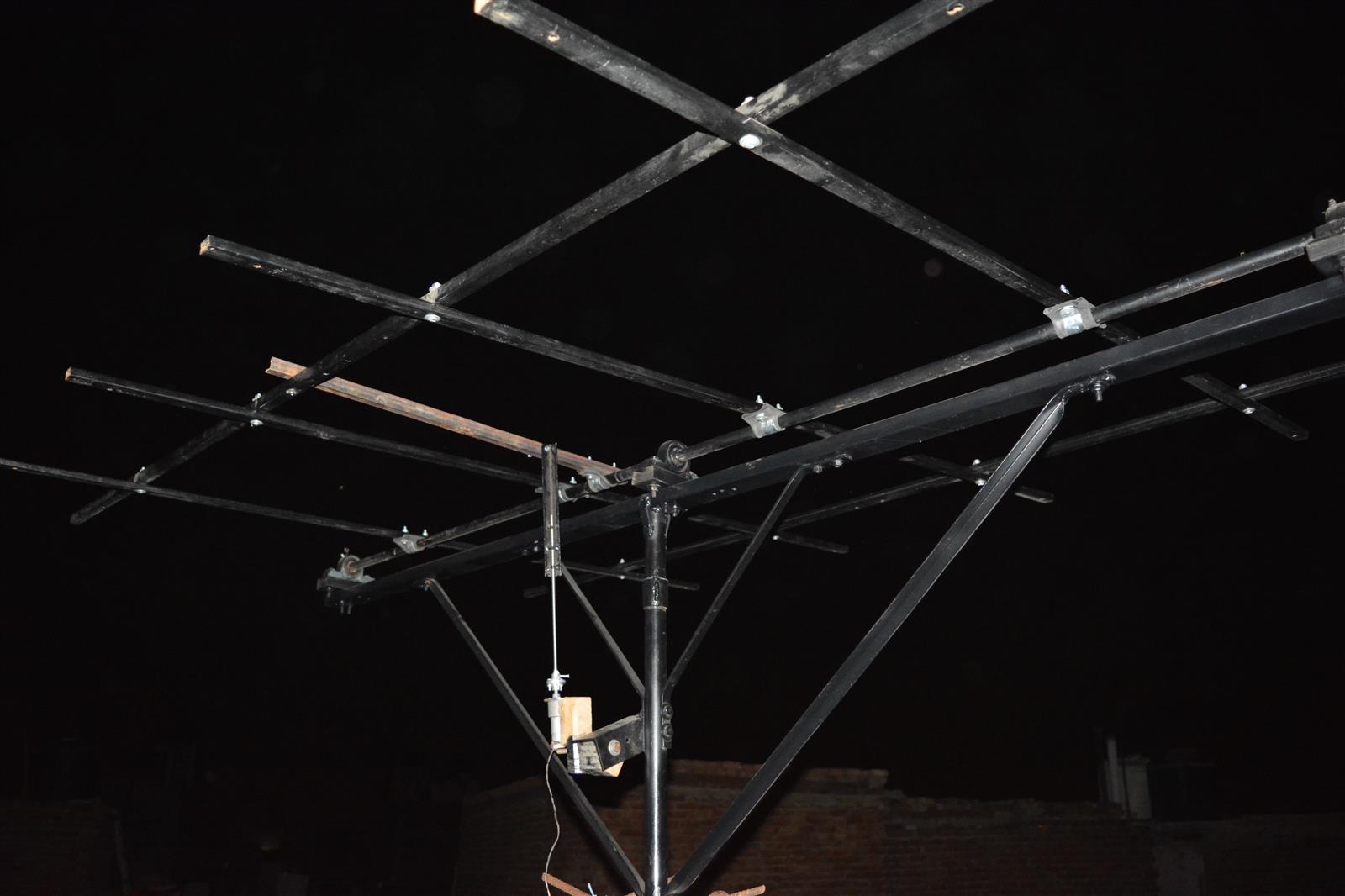
| MOUNTING PLATFORM | 1 No. | Dual Axis Tracker (that I have built myself) |
| DRIVE MECHANISM | Self designed, with the core of the system being controlled by the awesome open source Arduino Platform running with Atmel’s ATMEGA 328 running in its heart. | |
HOW THIS WORKS
The platform works with the help of an array of light sensors designed such that once the sun is near perpendicular to the light sensor array setup, it’s rays fall on all the sensors uniformly. Once the sun deviates a little, one or more sensors experience shadow because of the divider that has been put between the four light sensors. The MCU (Arduino, in this case) is used to feed in the data from the light sensor array which then makes the comparision based on the software code we have put inside the Arduino to take decisions based on the realtime information provided by the variety of arrays of sensors we will be feeding the data from, in the Arduino. Once the MCU takes a decision regarding the direction of the movement, it sends the relevant instruction to the H-Bridge Motor Driver based on the powerful L298N motor driver which can handle both of my 12v DC geared motors, having a stall torque of 45kgcm. The motor driver sends a signal, based on the input from the arduino for the relevant motor to move, in the direction, the MCU told the motor driver to move the motors in. Once this happens, and all the four sensors are again aligned such that the sun’s rays are again falling uniformly on all of them, with no shadow on any of the four sensors, the MCU tells the Motor driver to stop the motors till the time one of the light sensors again experiences shadow, which makes the aforementined process, start again.
As for the updates, they are not yet over. I have a lot of work yet to be completed. No, not about the functioning, as the system is up and running fine for around ten days now, since I first hooked up the panels to the charge controller, ten days back. What needs to be done is more of the stuff related to additional functionalities, that, I expect will add to the system’s geekiness, a lot more. Some of these things, that I can hgive you a glimpse, though, textually, here are – 1. Adding the Gyro sensor to: a) limit the movement of the panels and the tracker, at the extreme ends. b) realign the panel to east, in the morning after the earlier day’s tracking aligns the panels in the west. Right now, this is being done manually, though, I don’t have any issue in doing this manually, because, afterall, I do visit the rooftop daily, to take a stroll around my plants, and water them. 2. Redeploying the solar tracking functions. As it turned out to be, the actuator we had worked upon, for the test rig, was not capable enough of single handedly handing the extreme pressures of the solar panels, and if adding the additional stress exerted upon, by, say, a strong gust of wind blowing directly into the panels’ large surface area of around 3.2 square meters, hanging on, 30 feet above the ground, it is not much far from disaster. So, I decided to look for linear electric actuators, only to give up again, seeing the costs. And finally, I have thought up of a new design to make this happen, properly, and work on this new linear actuator is yet to start, as I am waiting for the parts. For the time being, I will just mount the new threaded rods I had bought, to replace the previously used 6mm threaded rods, which buckled down due to the extreme pressure of the modules and the frame. This new 10mm threaded rod in stainless steel, should ideally be capable enough to take care of the load, itself, so, I’ll go ahead and give it a try, for the time being.
For now, I will leave you guys with a couple of pictures of what’s happening these days and how the system, I have been posting updates on, for quite some time now, has transformed over time, to being the final product, something, that I had only envisaged, but had never visualised, the way it looks, and works, today.
 |
| The new mounting frame for the two solar modules. With the hand drill, and too less an experience, it was quite hard to get through this thing, especially, when one is working with steel. |
 |
| Both the solar modules, ready to be mounted on the tracker. The size, did appear to be intimidating, but then, I had to do this, at all costs, and so this was done, finally. |
 |
| Powering up! It felt great to see my dream realize. |
 |
| While I ultimately powered up, it was evening, and since there was still power, being generated, the charge controller chose solar power over the mains power, and the above shot is a result of the inverter batteries getting discharged, because of the loads were still extracting power, but there was not much being supplied to charge the batteries, so, this one shows the batteries being charged with mains power, after the power from mains to the inverter was restored after the solar out put was quite less. |
 |
| The modules facing the morning sun. For now, I have tied them (using the frame) up to make them stationary, and to check their movement under the influence of winds. Once the actuator is finally ready, the ropes will all be gone, atleast for the time the weather is good. I had to make separate arrangement for the shade net for my plants that are placed around this part. of the roof. |
 |
| The modules facing the morning sun. |
 |
| The peak output I could see/capture. |
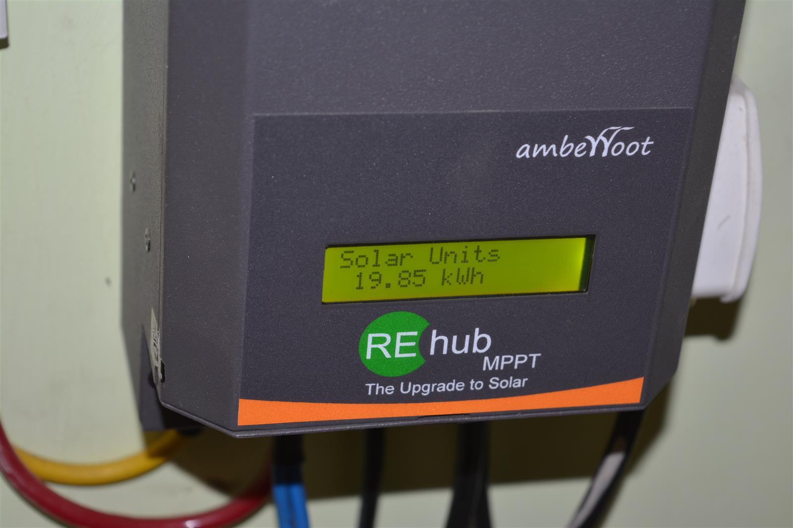 |
| Finally, the cumulative power generation by the solar modules, since I powered up the system up around ten days back. |
Since, the work on this is system is still underway, I will be coming up with a few more posts updating here, the work in progress, the status of the project and how it ends up, once the work is complete. And, maybe, my power bill as well, at the end of this month, to compare what’s the difference since I installed the system.